As stated above we add 1111 to 4 bit data in order to subtract 1 from it.
Design a combinational circuit for 4 bit binary decrementer.
It is made by cascading n full adders for n number of bits i e.
M a b a 0 0111 0110.
The storage capacity of the register to be incremented.
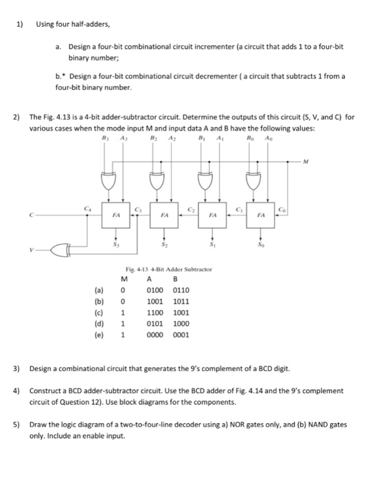
Determine the outputs of this circuit s v and c for various.
For this it simply adds 1 to the existing value stored in a register.
The design procedure for combinational logic circuits starts with the problem specification and comprises the following steps.
The storage capacity of the register to be decremented.
The adder subtractor circuit has the following values for mode input m and data inputs a and b.
In each case determine the values of the four sum outputs and the carry c.
A0 a1 a2 a3 for a b0 b1 b2 b3 for b.
Hence a 4 bit binary decrementer requires 4 cascaded half adder circuits.
Determine the inputs and outputs.
Hence a 4 bit binary incrementer requires 4 cascaded half adder circuits.
Hence a 4 bit binary decrementer requires 4 cascaded full adder circuits.
Lets consider two 4 bit binary numbers a and b as inputs to the digital circuit for the operation with digits.
This problem has been solved.
The increment micro operation adds one binary value to the value of binary variables stored in a register.
Design a four bit combinational circuit decrementer a circuit that subtracts 1 from a four bit binary number.
In this work we improve the performance of the binary adder circuit to increase the speed of the operation.
For instance a 4 bit register has a binary value 0110 when incremented by one the value becomes 0111.
Design a four bit combinational circuit incrementer a circuit that adds 1 to a four bit binary number.
As stated above we add 1111 to 4 bit data in order to subtract 1 from it.
Binary decrement using full adder 4 bit fa fa fa fa s3 s2 s1 s0 cout cin 1 a3 1 a2 1 a1 1 a0.
This circuit requires prerequisite knowledge of exor gate binary addition and subtraction full adder.
A circuit that adds one to a 4 bit binary number the circuit can be designed using four half adders.
Design a bcd to 7 segment decoder circuit for segment e that has a 4 bit binary input and a single output 7e specified by the truth table.
It is made by cascading n half adders for n number of bits i e.
However our main focus in this paper is to design a binary incrementer and decrementer circuit for a qca system.
The increment micro operation is best implemented by a 4 bit combinational circuit incrementer.
A binary increment is required to perform an increment of binary numbers in the alu.
4 13 is a 4 bit adder subtractor circuit.
Design a 4 bit combinational circuit decrementer using four full adder circuits.

